5. Data Transmission
Objectives:
- Describe the advantages of using digital interconnections
over analog interconnections.
- Identify the two components of a digital interconnect format.
- Define word clock, bit clock.
- Differentiate between embedded clock and dedicated
clock.
- Given one or more devices, determine a proper
clocking scheme for direct
connect, daisy-chain, or star topologies.
- Define the relationship between Master and Slave clocking.
- Select the appropriate
clock sources for devices.

Transmitting Audio Data
Two methods:
Analog
- Simpler connection and transmission - no clock information
needed
- Potential for signal compromises such as polarity
inversions, gain changes, hum and noise, high frequency loss
- Loss of data
quality through multiple conversions

Digital
- No loss of data integrity - remain in digital domain
- Formats ensure data integrity - no gain changes, polarity shifts, or noise
introduction
- More complex process for transmission
Digital Data Transmission Formats in General
Numerous data formats have been devised for digital interfacing.
These formats define such potential variables as:
- electrical
characteristics
- physical connectors
- how the digital audio is encoded
- the rate at which data
is transferred
- the bit resolution and sample rate
- extra housekeeping
and error-detection information.
Components of Digital Audio Transmission
All digital transmission
formats must have:
- a data communication channel
- common clock synchronization
Digital clock
Digital audio transmission requires
that the sample timing of each device be synchronized together.
i.e. The device receiving each of the samples
per second must know
 |
Do you know when each sample to the
left starts and stops?
1) HOW many samples per second are being sent
(44.1k, 48k, 96khz etc),
2) How long the samples are (i.e. 16 bits long, 24 bits long, etc)
3) Exactly when each one starts & ends.... a giant stream of 1's & 0's
don't mean much if you don't know how to break each down into an audio
sample. |
If the clocks are not sync'd, errors will manifest:
- distortion
- clicks and pops
- muted audio.
From a user's point of view, the only difference between
analog and digital transmission is that digital requires a timing reference.
The timing reference is a known
as the clock - a signal
that identifies when a sample of audio is executed.

Types of Clock Signals
Internal clock
- An internal clock is a clock that has
no outside reference.
- All digital devices can generate their clock internally.

Word clock
- Defines when a sample word is to be processed or executed.
- Frequency is equal to sample rate.
- It can also be referred to as sample
clock.

Bit clock
- Synchronizes at the bit
level instead of word by word.
- Sample information (sample start) embedded in the data
- Example: AES clock
Other clock sources
- Older Pro Tools can use a Superclock,
a dedicated clock signal which is 256 times the word clock.
- Current Pro Tools HD uses a system called loop sync, interconnecting all
pieces together in a loop
- A video reference signal can be used to extract a digital
clock
- Positional sync systems (SMPTE or MIDI time code)
can time-align devices, but are not accurate for sample clocking, and cannot
be used as a reliable digital clock
- TIMECODE is NOT digital audio Clock. Timecode gives
an address on the tape
- (i.e. this spot in the song is 1hr:3min:4sec:11frames
into the song,
- a digital sample clock says "here is a 24 bit, 44.1k sample,
now, now, now, now, now, now, now, etc)


Transmission of Clock
Two basic methods of clock signal is transmission:
Embedded clock
- A system in which the clock
is extracted from the audio data that is being sent.
- The structure of the transmitted
data is such that there is a regular transition
of level for each bit interval.
- The
receiving device can use the transitions in
the incoming data to establish a clock signal.
- AES/SPDIF/ADAT Optical, etc can all use "embeded clock"

Dedicated clock
- A system that uses
a separate connection for transmitting and receiving a clock signal.
- Typically, this clock signal will be on a 75-ohm
coaxial cable using BNC-type connectors.


- Some devices use a dedicated AES input for clock signal
only (no audio data transmitted)

Is one better?
- Embedded clock is inherently easier to use
- Some manufacturers argue that a faster clock is more
accurate
- Some experts argue that changing data (inherent in an
embedded clock) can altar the timing of the clock signal.
- The important data being conveyed is WHEN the SAMPLE
should be processed
Clocking Master and Slaves
Digital audio equipment has the capability of
determining its clock source - either internal or external.
- internal - that device will follow its
own internal clock, ignore any incoming signal.
- external -
the device depends on an external clock (embeded in the digital input,
or over the BNC word clock) signal to establish its internal clock.
Absolutely, positively, without a shadow of a doubt, there
can be only one clock source, or clock master. All other
devices must receive their clock reference from this one master; in essence,
they become clock slaves.
One master, all others are slaves
to that master.
The master uses an internal reference, and the
slaves use an external reference, sourced from the master.

Establishing the Clock Reference
Two pieces of gear
- Since there are only two pieces (and one interconnection),
clocking can be easily resolved.

- Use of an external clock signal is preferred; however,
using the embedded clock will suffice.
Multiple pieces of gear
- Remember that there should only be one master
clock reference.
- If more than two pieces of gear, use a
dedicated clock signal and transmit it to each device.
- This signal may be generated
by one of the devices or it may
come from a dedicated clock generator
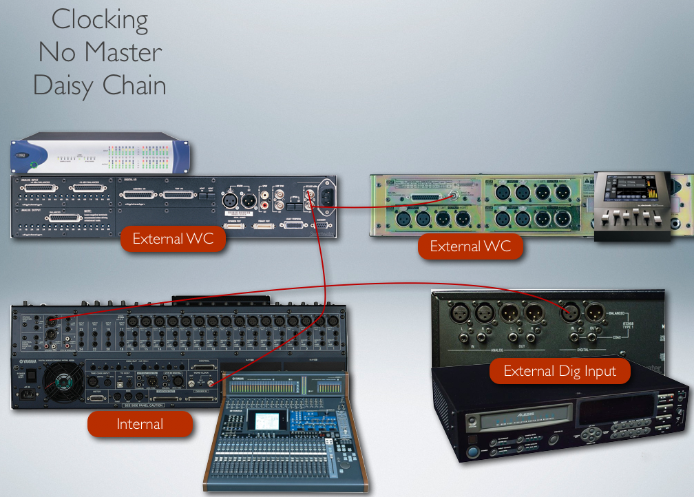
Topologies
Daisy-Chain, or Loop
- Clock signals can be looped through a device (similar
to the THRU connection on MIDI gear).
- Using the OUT port violates the "one master" rule. The
the signal at the OUT connector is generated by this device's internal
clock.

Word clock with a
THRU port
Star
- Start topology runs a dedicated line to each piece of gear from the master
- if there are several pieces of gear, a star topology is preferred
Example connection schemes
Two devices: 
Click here
to view proper settings & connection
Three devices: 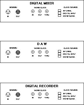
A proper
connection A and B
With Real Gear
